An electrical circuit is a system formed by a set of interconnected electrical elements. It has one or more closed paths that can be traversed by an electric current.
An electric current is the movement of free electric charges in an orderly fashion. Normally these charges are electrons that move from the negative pole to the positive pole. Depending on the movement described by electric charges, we distinguish two types of currents: direct current and alternating current.
The intensity of current indicates the amount of electrons that will circulate through a section of a conductor during a determined time.
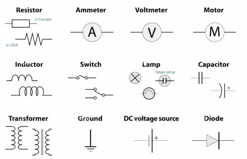
Electrical diagrams or schematics with standardized electronic symbols are used to represent electrical circuits.
Components of an electrical circuit
The basic components of an electrical circuit are as follows:
-
Generator: The electric generator is the element in charge of generating the electric current maintaining a potential difference between the ends of the circuit. For example, a battery or a photovoltaic panel.
-
Conductor: the current conductor is where the electrons driven by the electric generator move. The material used must be electrically conductive. The most conductive elements on the periodic table are silver, copper, and gold.
-
Electrical resistance: resistances are elements that oppose the passage of electrical current. They are the circuit elements that lose the most useful energy in the form of heat according to Joule's law.
-
Receptors: Receptors convert electricity into another type of energy. Light bulbs and electric motors are examples of receptors.
-
Control elements: the function of these elements is to cut off or direct the flow of current within the circuit. Some examples are pushbuttons, switches and toggles.
-
Capacitors: A capacitor is an element with the capacity to store electrical energy and that it can later release.
-
Inductors: They store energy in the form of a magnetic field when current flows through them. They are common in filter circuits and timing circuits.
-
Diodes: Allow current to flow in only one direction. They are used in rectifier circuits and to protect polarity sensitive components.
-
Transistors: They act as switches or amplifiers of electrical signals. They are essential in digital electronics and audio amplifiers.
The elements of an electrical circuit can be connected in series and parallel. For example, in serial receivers the receivers are connected one to one with each other.
In series circuits, the current intensity is identical in all the elements. However, in parallel circuits in which a current is flowing, the currents add up.
Types of electrical circuits
There are several types of circuits, each with specific characteristics and applications. Below are some of the most common types:
Series circuit
A series circuit is one in which components are connected one after the other, creating a single path for current to flow. The current is constant throughout the circuit, which means that the same current passes through each component in sequence.
The voltage is divided between the components, which means that the sum of the voltage drops across each component equals the source voltage. If a component in a series circuit is disconnected or removed, all current flow in the circuit is interrupted.
Parallel circuit
A parallel circuit implies that components are connected in multiple paths for current to flow. The voltage is the same across all the components of the parallel circuit, but the current is divided between them.
If one component in a parallel circuit is disconnected or removed, the others continue to function without interruption.
Mixed circuit
A mixed circuit is a combination of series and parallel circuits.
There can be multiple branches in parallel, and within each branch there can be components connected in series.
Mixed circuits are commonly used in applications where a combination of functions is needed, such as complex electrical circuits.
Circuit in direct current (CC or DC)
A direct current circuit implies that current flows in only one constant direction.
This type of circuit is commonly found in batteries, portable electronic devices, and DC power supply systems.
Circuit in alternating current (AC)
In an alternating current circuit, the direction of the current is periodically reversed, oscillating between positive and negative values.
Most home and business power grids use alternating current for power distribution.
Three-phase circuits
Three-phase circuits are used in industrial and commercial applications to efficiently supply electrical power.
They consist of three phases of alternating current 120 degrees out of phase with each other, which allows a more balanced and efficient transmission of power.
Digital circuits
Digital circuits are used in electronics to process digital signals, which are represented by discrete values (0 and 1).
Common examples include logic gates, flip-flops, microcontrollers, and digital integrated circuits.
Analog circuits
Analog circuits are used to process analog signals, which are continuous in their representation.
Examples include audio amplifiers, radio circuits, and sensors.
Power circuits
These circuits are used in high power electrical systems such as electrical power distribution systems and motor control systems.
Fundamental laws of electrical circuits
The fundamental laws of electrical circuits are principles that govern the behavior of electric current and voltage in electrical circuits. These laws are essential for the analysis and design of electrical circuits.
Among the fundamental laws, the following stand out:
Ohm's law
This law establishes the basic relationship between current (I), voltage (V) and resistance (R) in an electrical circuit. Ohm's law is expressed by the following equation:
V=I⋅R
Where:
Ohm's law states that the current in a conductor is directly proportional to the applied voltage and inversely proportional to the resistance of the conductor.
Kirchhoff's laws
Gustav Kirchhoff formulated two fundamental laws that apply to complex electrical circuits for the analysis of currents and voltages:
-
Kirchhoff's Current Law (law of nodes): At any node in a circuit (a connection point where several conductors converge), the algebraic sum of the currents entering the node is equal to the algebraic sum of the currents leaving of the node. This is based on the principle of conservation of charge.
-
Kirchhoff's Voltage Law (mesh law): In any closed loop or mesh in a circuit, the algebraic sum of the voltage drops around the mesh is equal to the algebraic sum of the applied voltages across the mesh. This is based on the principle of conservation of energy.