
Electric pressure, also known as voltage or electrical potential difference, is a fundamental concept in electrical engineering and physics. It represents the difference in electrical potential between two points in an electrical circuit. While it is often referred to as voltage, this "pressure" plays a vital role in determining how electricity flows through conductors.
This electric pressure indicates the amount of energy required to move electrical charges from one point to another. It is the difference between the potential energy of a charge at two different points, caused by the presence of an electric field, divided by the value of the charge itself.
In simple terms, electric pressure is the force that pushes electric charges, creating an electric current as they move from a higher potential to a lower potential. Under stationary conditions, this potential difference is equivalent to the work done to move a unit charge through the electric field.
When two points in a circuit are connected by a conductor, the electric pressure between them causes charges to flow through the circuit, generating electric current. This flow is a result of the charge moving from the point of higher potential to the point of lower potential.
The Origin of Electrical Voltage
The concept of voltage was first introduced by Alessandro Volta, who used it to explain the energy required to move charges in a circuit. Volta, along with other concepts like electric capacity and electric charge, helped shape our modern understanding of electric pressure and its role in electrical systems.
Today, voltage is measured in volts (V), and the device used to measure it is called a voltmeter. The voltmeter determines the electric pressure or potential difference between two points in a circuit.
Explaining Electric Pressure with a Hydraulic Analogy
 A simple way to understand electric pressure or voltage is through a hydraulic analogy. Imagine a closed pipe filled with liquid. If the ends of the pipe are at different heights, a pressure difference is created between the two points. This pressure difference is similar to the electric pressure or voltage in an electrical circuit.
In this analogy, the electric potential difference between the poles of a generator corresponds to the pressure difference in a hydraulic system. The flow of liquid through the pipe is akin to the flow of electric current through the conductor. Just as the liquid flows from high pressure to low pressure, electrons (the carriers of electric current) move from a point of higher potential to a point of lower potential.
What is the Unit of Electric Pressure (Voltage)?
Voltage, or electric pressure, is measured in volts (V). A volt represents the potential difference that drives the flow of electric charge. To measure this potential difference, we use a voltmeter, which shows the voltage between two points in a circuit, helping us understand the force behind the flow of electric current.
Understanding Current Direction in an Electrical Circuit
In an electrical circuit, current direction is defined by the flow of positive charge carriers. Historically, it was believed that electric current flows from positive to negative, and this convention is still widely used. However, in most materials, electrons are the actual carriers of the current, and they are negatively charged. This means that electrons flow in the opposite direction to the conventional current.
Despite this, the current flow is still defined as moving from the positive terminal to the negative terminal of a power source, such as a battery. In circuit diagrams, the arrows that indicate current flow are based on this conventional direction, representing the movement of positive charges.
Voltage in a Static Electric Field
In a static electric field, electric voltage or potential difference is defined as the amount of work per unit charge done by the electric field to move an electric charge from one point to another. Since the field is conservative, the voltage depends only on the starting and ending points, not the path taken.
This means that the electric pressure or voltage between two points in a static electric field is constant, regardless of the path taken by the charge.
Induced Voltage: Electromotive Force from a Changing Magnetic Field
Another fascinating aspect of voltage is how it can be generated by a changing magnetic field. When a coil encloses an area with a changing magnetic flux, an electromotive force (EMF) is induced, creating an electric potential difference (voltage) across the coil.
This is the principle behind induced voltage, which occurs when a conductor moves through a magnetic field, generating an electric potential difference in the conductor. This phenomenon is fundamental in devices like electric generators and transformers.
Ohm's Law and Voltage in Electrical Circuits
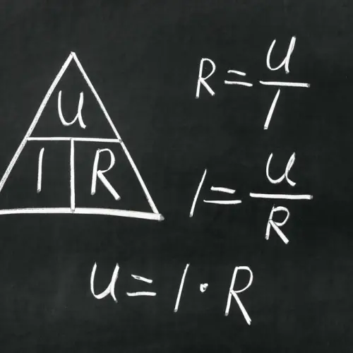 One of the most fundamental laws in electrical circuits is Ohm’s Law, which governs circuits with purely resistive loads. Ohm’s Law states that the electric pressure (voltage, V) across a resistor is proportional to the electric current (I) flowing through it, and the resistance (R) of the material:
V = I·R
In simple terms, the resistance of a component causes a voltage drop as the electric current flows through it. This relationship is essential for understanding how circuits behave, especially when components like resistors are involved.
Furthermore, the electric current passing through a resistive component results in power dissipation. The amount of power dissipated is calculated as the product of the voltage (V) and the current (I):
P = V·I
This power loss is known as the Joule effect and is a crucial concept in electrical systems, as it represents the conversion of electrical energy into heat.
What Does a Coulomb of Charge Mean?
A coulomb (C) is the standard unit of electric charge in the International System of Units (SI). One coulomb is equivalent to the charge transferred by a steady current of one ampere in one second.
To put it into perspective, one coulomb is equal to approximately 6.241 x 10^18 electrons. This measurement helps quantify the amount of electric charge that passes through a conductor, which is essential when considering electric pressure in circuits.
Electric Pressure and Voltage Classifications
The classification of electric pressure or voltage can vary depending on the type of current (AC or DC) and the specific electrical system. For instance, the CEI-EN 50110-1 standard classifies voltage into different categories based on its level, as follows:
| Category | In Alternating Current (AC) | In Direct Current (DC) |
|---|---|---|
| Very Low Voltage | 0 ≤ 50 V | ≤ 120 V (in rippled DC) |
| Low Voltage | 50-1,000 V | 120-1,500 V |
| Medium Voltage | 1-30 kV | 1.5-30 kV |
| High Voltage | > 30 kV | > 30 kV |
These categories help identify the potential hazards associated with different voltage levels, as well as the necessary safety precautions when working with electricity.