The Kaplan turbine is a hydraulic turbine that uses small gradients, up to a few tens of meters, but with a massive flow of water rates, from 200/300 m³ / s. Kaplan turbines are widely used throughout the world in hydropower plants for electrical power production.
Constructively, this hydraulic turbine is a propeller, where the blades can be oriented since the water flow varies. This regulation allows the performance to remain high up to 20-30% of the nominal flow rates.
The turbine is usually equipped with fixed stator deflectors that guide the flow. Turbine efficiency can be optimized for a range more expansive than the ideal flow rate. This regulation is carried out using an orientation system of the stator deflectors when the flow varies.
The liquid reaches the Kaplan turbine through a spiral-shaped conduit that feeds the entire circumference. The water then passes through a distributor that gives the fluid a spinning rotation. This rotation is essential to impart motion to the impeller, where 90 ° deflected flow reverses it axially.
Unlike the Francis turbine, it is possible to recover energy thanks to the diffuser in the exhaust.
These turbines are used in hydroelectric power plants with low head heads with low water pressure. The entire head of the site (from forebay level to tail race level) can be captured.
The Kaplan turbine was invented in 1913 by Austrian professor Viktor Kaplan. The invention represented a technological boost to hydropower and renewable energy. In the early years, Kaplan struggled with cavitation problems and abandoned his work in 1922 due to health problems. Voith continued his work and developed the design further.
What is the performance of a Kaplan turbine?
The Kaplan turbine allows working with efficiencies of up to 90%.
A mechanical engineering system makes it possible to change the impeller blades’ orientation adapting to the current flow. It is because each distributor setting corresponds to one direction of the blades. The blades of the Kaplan turbine has twist along its length.
This feature allows you to work with very high performances in a wide range of flows.
These types of turbines are built with double regulation or with simple regulation. The double regulation allows better use of low flow rates but makes it more expensive than a Francis of equal power.
Features of the Kaplan turbine
The Kaplan turbine is an axial flow turbine; this means that the fluid enters and exits (from the turbine) in an axial direction, to the impeller’s rotation axis. Unlike the Francis turbine, it does not rotate during the transit phase in the impeller.
In terms of geodetic jumps, with which the Kaplan turbine operates, we arrive at shallow values (compared to the Francis turbine itself ): the maximum value of Hg ( useful geodetic jump ) is about 30 m.
With a propeller turbine, the regulation is practically zero, so it can only work for a specific range, so the distributor is not even adjustable.
This type of hydraulic turbine can be manufactured with a horizontal, inclined, or vertical axis.
The use of Kaplan slow-motion turbines reaches maximum heads of around 80 m and flows up to 50 m³ / s. It partially exceeds the field of use of fast Francis turbines, which get drops of less than 10 m and can exceed 300 m³ / s
It is common to use both propeller and Kaplan turbines: propeller turbines will run at full capacity, and any excess fluid will go to Kaplan turbines, whatever their size.
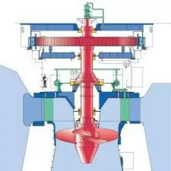
What are the components of a Kaplan turbine?
The main parts of the turbine are:
-
Scroll Casing: It is a spiral type of casing that has a decreasing cross-section area.
-
Guide Vane Mechanism: It is the only controlling part of the whole turbine. When the power output requirements rise, it opens wider to allow more water to hit the blades.
-
Draft Tube: The pressure at the exit of the runner of Reaction Turbine is generally less than atmospheric pressure.
-
Runner Blades. It is the most crucial component. It is the rotating part which that its shaft is connected to the shaft of the generator.
Operation and mechanical engineering
-
The water enters the turbine through a spiral distributor.
-
Subsequently incident on a distributor bladed with adjustable blades attached directly to the central shaft of the turbine.
-
The motion that characterizes the fluid in this section is of a centripetal type, with a strong tangential component.
-
The water passes through a non-bladed toroidal channel in which the radial effect of the fluid motion is eliminated.
-
Subsequently, we will see the fluid affect the impeller blades, with the consequent transfer of its mechanical energy to the impeller itself.
-
There is the rotation of the impeller around its axis due to the reaction force of the water.
-
The tangential component’s effect is canceled, and the flow is free to be discharged in the section with a divergent section ( diffuser) in the axial direction.