A water turbine is a machine that transforms the energy of a water flow into mechanical energy by means of a system of rotating blades. This mechanical energy can be used to power another machine or an electric generator.
A simple turbine consists of a single rotor with blades, which provide energy exchange with the flow. The impeller blades deflect the flow stream to transform kinetic energy and pressure energy, or to exchange fluid momentum with a moment of force on the shaft.
The moment of force on the shaft causes the turbine to rotate, generating rotational kinetic energy. If the turbine is connected to an electric generator, electricity is obtained. In other cases, this energy is used directly to obtain mechanical work.
In most hydraulic turbines, the water flow is either axial or radial. However, in a cross-flow turbine, the water passes through the turbine blades in a transverse direction twice, first in the direction of the axis and then away from it.
Classification: types of hydraulic turbines
Hydraulic turbines, used in hydraulic power installations, can be classified according to two criteria.
A first classification is based on the way they work and they can be action or reaction turbines. Action turbines only use the speed of the water flow, while reaction turbines also use the loss of water pressure inside the turbine.
Depending on its design, a turbine can be:
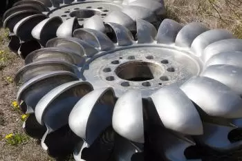
1. Pelton turbine
Pelton turbines are cross-flow, partial-admission action turbines. One of the most efficient types of hydraulic turbine.
The Pelton turbine consists of a wheel (impeller or rotor) fitted with spoons on its periphery. These spoons are specially designed to convert the hydraulic energy of a jet of water that strikes the spoons.
Pelton turbines are designed to exploit large, low-flow hydraulic jumps.
2. Francis turbine
The Francis turbine is an internal flow reaction turbine that combines both radial flow and axial flow concepts.
It consists of a fixed part with curved guides called deflectors (or distributor) and a mobile part with blades, also curved, called rotor. The inclination of the deflectors can be adjusted to adjust the flow applied to the blades, thus regulating the speed of the turbine.
It is a type of turbine very appropriate for medium-high jumps with medium flow rates, being capable of producing very high powers.
3. Kaplan turbine
Kaplan turbines are axial flow reaction water turbines, with a roller that operates similarly to a ship's propeller.
They are used in hydroelectric power plants with small waterfalls. The large blades or vanes of the turbine are driven by high-pressure water released through a gate.
The water flows in the same direction as the axis. In addition to being able to regulate the inclination of the deflectors, the inclination of the rotor blades can also be regulated. In this way, the turbine adapts to the power needs of each moment. It is used in installations with small falls and large water flows, such as those in reservoirs.
4. Propeller turbine
Like all hydraulic turbines, the propeller turbine consists of a guide ring with guide vanes and a rotor. Depending on the flow, the propeller turbine can be designed with single control (guide vane adjustment) or double control (guide vane and rotor speed adjustment).
The guide vanes adjust the volume of water flow entering the rotor. At the same time they change the direction of the flow so that it enters the rotor with its own torque as the rotor turns.
From an efficiency point of view, the propeller turbine can be compared to a Kaplan turbine. In addition, the electronic regulation of a propeller turbine makes it possible to achieve low water operating points that cannot be achieved with a Kaplan turbine.
Parts of a hydraulic turbine
The main parts of a hydraulic turbine are:
- Rotor or Blades : These are the moving parts of the turbine. They are designed to be hit by the water flow, causing it to rotate. The shape of the blades depends on the type of turbine, such as Pelton, Francis or Kaplan.
- Shaft : Connects the rotor to a generator or mechanical system. The shaft transmits the rotational motion of the rotor to the electricity generating machine or other useful device.
- Casing : The structure that surrounds and protects the rotor, maintaining the direction of water flow and facilitating the transfer of energy from the water to the rotor. It also helps control the flow of water into the rotor.
- Turbine (Body) : The body is the part of the turbine that contains all the components. Generally, it is where the water enters, is directed towards the blades, and is expelled after having transferred its energy to the rotor.
- Blade angle : In some turbines, especially Kaplan turbines, the blade angle is adjustable to optimize efficiency based on flow rate and water drop height.
- Inlet Duct (Intake Pipe or Channel) : This is the duct through which water reaches the turbine, channeling the water flow towards the turbine blades. Water pressure and speed are important factors for turbine performance.
- Regulator or Governor : It is a system that controls the rotation speed of the turbine by adjusting the flow of water that reaches the blades. It allows the turbine to operate at its maximum efficiency.
- Diffuser : In some turbines, the diffuser is located at the end of the turbine and has the function of reducing the speed of the water while increasing the pressure before it exits into the environment. This helps improve the efficiency of the turbine.
- Valves : In many hydraulic systems, valves are used to control the amount of water entering the turbine. Valves are also essential for safely starting or stopping the operation of the turbine.