In electrical engineering, a three-phase system indicates a combined system of 3 alternating current circuits (for a system of production, distribution and consumption of electricity) that have the same frequency.
Compared with single-phase installations, in a three-phase installation the cost of materials and electrical cables is reduced by 25% for the same amount of electrical energy transformed and generated.
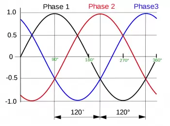
Three-phase current is the flow of electrical energy formed by three single-phase alternating currents of the same frequency and amplitude (and therefore, effective value) that present a certain phase difference between them, around 120 °, and are given in an order determined.
To find out if your installation is single-phase or three-phase, you can do it in two ways:
- Observing the ICP (Electric Power Switch), they can be distinguished by the number of levers, if it has three or more levers it is a three-phase system. If you have only 2, it is a single phase system.
- Observing your electricity bill. If the contracted power is between 380 to 400 volts (V), it is a three-phase installation.
Three-phase current characteristics
Each of the single-phase currents that make up the system is designated by the name of phase.
A three-phase system of voltages is said to be balanced when its currents are equal and are symmetrically out of phase. When any of the above conditions are not met, the voltage system is an unbalanced system or an unbalanced system. This would be the case of different voltages in the different phases or different lags between them.
A system of unbalanced loads is the set of different impedances that cause currents of different amplitudes to flow through the receiver or with phase differences between them different from 120 °, although the system or line voltages are balanced or balanced.
There are two types of connection, triangle and star. In star, the neutral is the junction point of the phases.
Advantages of three-phase current
The three-phase current system presents a series of advantages, such as the reduction of electrical energy consumption in the power transmission lines (finer wires than in an equivalent single-phase line) and of the transformers used.
The three-phase system also presents a high performance of the receivers, especially electric motors, to which the three-phase line feeds with constant and non-pulsed power, as in the case of the single-phase line.
Briefly we could list the following advantages of three-phase current systems.
- The output of three-phase machines is always higher than those of single-phase machines of the same size, about 1.5 more. Thus, for a given size and voltage, a three-phase alternator takes up less space and is also less expensive than single-phase ones of the same size.
- For transmission and distribution, three-phase systems need less copper or less conductive material than a simple single-phase system given in volts amperes and voltage so the transmission is much more economical.
- It is possible to produce rotating magnetic fields with stationary windings using the three-phase system. For this reason, three-phase motors are self-starting.
- In a single phase system, instantaneous power is a function of time and fluctuates. This power fluctuation causes considerable vibrations in single phase motors. Therefore, the performance of single-phase systems is poor. However, the instantaneous power in three-phase systems is constant.
- Three-phase systems give a stable output.
- A single-phase supply can be obtained from three-phase circuits but three-phase cannot be obtained from a single-phase motor.
- The power factor of single-phase motors is poor relative to equivalent three-phase motors.
- For converting machines such as rectifiers, the output voltage in direct current is more uniform if the number of phases is increased.
In what applications are three-phase systems used?
The generators used in power plants are three-phase, since the connection to the electrical network must be three-phase (except for low-power plants). Three-phase is widely used in industries, where machines are powered by motors for this voltage.
In a domestic photovoltaic solar energy installation, the most common is that they are connected to a single-phase system. However, there are solar kits that provide a three-phase current.
Large solar power plants are three-phase because the connection to the electrical grid must be three-phase.
Diagrams of connection types in three-phase systems
The connection of loads in daily practice, for example the windings of an electric motor or a transformer, can be done in two ways. Generally, in the machines there is a box (terminal block) in which it is possible to configure the circuit by means of jumpers, in order to adapt the operation to phase-to-phase voltages of 400 or 230 volts.

Star connection diagram (symbol: Y)
Delta or delta connection diagram (symbol: Δ)
In some large three-phase asynchronous motors designed to work with the windings connected in delta (therefore subjected to voltage between phases) it is possible to perform a star start.
The delta configuration presents between two lines (phases) an equivalent impedance equal to the value of the impedances used (I), while in the star configuration the value is greater than a root factor of 3.
What is the neutral point of a three-phase system?
In the star configuration there is a central point where one terminal of each impedance converges. This point is called neutral. The electric potential present at the neutral point is the vector sum of the phase voltages, which in a balanced and symmetric system has zero value.
If the system becomes unbalanced or the voltages become asymmetrical, the neutral point moves away from the center of the star. In this case, the phase-neutral voltages will not be equal to each other.
What is the CEI color code?
The EN 60446 standard (Identification of conductors using colors or numerical codes) created by the ECI establishes a precise color code for electrical cables:
-
Phase R or L1: brown
-
S or L2 phase: black
-
Phase T or L3: gray
-
Neutral N: Blue
-
Protection / floor / screen: yellow - green
Manufacturing industries must comply with this code. If a line is three-phase without neutral, it is allowed (but not recommended) to use the color blue for the phases. Three-phase cables with a gray, a brown, and a black conductor (for example) are commonly found on the market, which are joined together for use on a three-phase line without neutral.
In single-phase systems, being part of a three-phase system, the neutral is blue, the phase can be black, brown or gray and the protection / earth yellow-green.
This distinction has been in effect since 1990; therefore, on older systems, colors may not be honored.